Bolt sizing is an extremely important element when designing machines and metal structures in general, with this article we will clarify many aspects related to the physics of bolted joints.
Bolts classification
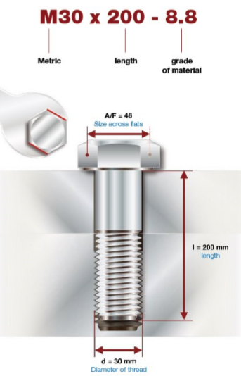
Each bolt is classified through a series of construction data, the most important are:
- The definition of the type of thread (M corresponds to metric);
- The diameter of the threaded part (in the example 30mm);
- The length of the part subjected to preload and therefore to elongation;
- The grade of the material or strength class;
The bolts can be made with unalloyed steel (burnished and hot dip galvanized) or alloyed with low or medium carbon content, but for those with high strength the material is subjected to a hardening and tempering treatment.
Bolts strenght class
The strength class represents the breaking strength and yield strength of the bolts, it is represented by two numbers separated by a dot and the common resistance classes encountered in industrial applications are 4.6, 5.6, 6.8, 8.8, 10.9 and 12.9.
Analyzing in detail these values it is possible to define, taking as an example a bolt of class 8.8, the following:
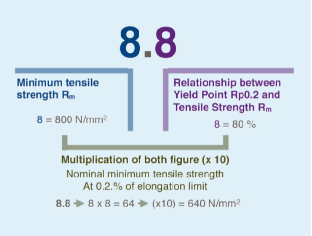
Rm, that is the first value, represents the breaking load, whereas the second value represents the percentage compared to Rm in which is located the yield strength. Both values are expressed in N / mm2 and if multiplied by the core area (in mm2) we will have the values expressed in kN, a much more familiar unit of measurement.
For example:
- Bolt M30 10.9
- Core area: 557mm2
- Yelding point: 900N/mm2 x 557mm2 = 501KN
- Breaking point: 1.000N/mm2 x 557 mm2 = 557KN
The nominal preload usually found in the tables is calculated at 70% -75% of the yield strength, however a different% may be used for specific cases.
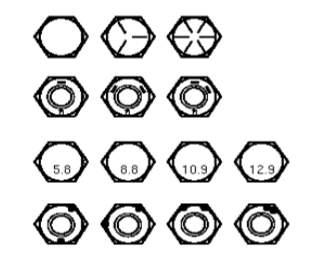
Strength classes can also be indicated with symbols on the head of the bolt, such as can be seen in the drawing below.
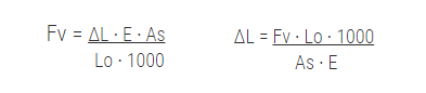
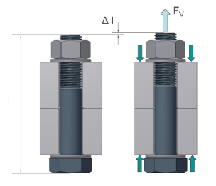
The physics of the bolts
The elongation
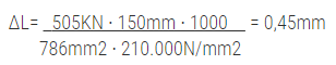
A bolt is an elastic joint that provides a bonding force when subjected to a load, the application of a FV load generates the elongation ΔL of the bolt, the generated FV force is proportional to the elongation ΔL according to the following formula:
 |
ΔL= Elongation
E= Young module (210.000N/mm2) Lo= Starting lenght As= Resistant area |
For example:
- Bolt M36x150 10.9
- As: 786mm2
- Lo: 150mm
- Fv: 505KN
Elongation at break and nut rotation
The following table represents the elongation percentage based on the strength class at which the bolt will arrive at the breaking point.

It is possible through a simple calculation to determine the number of revolutions (and therefore the degrees of rotation) with which it will be reached the break, let's see how:
- Bolt M30 x 100 10.9 pitch 3,5
- % of elongation 10% > Elongation of 10 mm > 10mm/3,5= 2,8 revolutions > 1.028°
How is controlled elongation generated?
The elongation, and therefore the forces in the bolt, is generated by supplying a torque to the screw, as seen in the previous paragraph it is possible to determine how many degrees of rotation are needed to generate an elongation of x millimeters.
The relationship between the force in the bolt (preload) and the torque to be applied to the nut is expressed through the following formula:

d: nominal diameter
K: global coefficient (friction, shape) [0,12-0,3]
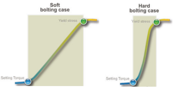
Deformation curve of bolts
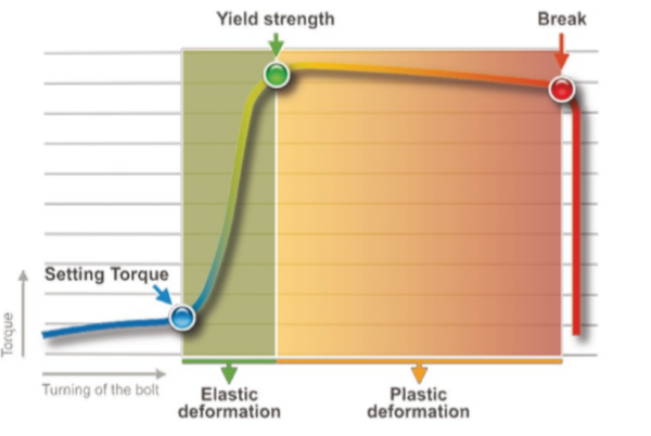
The deformation curve of the bolts is the main graph that characterizes the behavior of the bolt and links the torque applied to its elongation.
- The initial phase, called the approach phase, takes us to the Setting Point.
- The second phase is the elastic one which ends in the green point called the Yield Point.
- The third phase is called the plastic phase (or permanent deformation phase).
- The fourth and final stage is where the bolt breaks.
Approach phase
The approach phase is the phase that foresees the approach of bolt and nut up to the close contact of the parts. At this point there is no substantial elongation and therefore preload is negligible.
And is also the point from which the angular rotation is calculated in the case of torque + angle tightening.
Elastic deformation
Elastic deformation is the most important phase because the necessary elongation is provided to reach the required strength.
The limit is represented by the Yield Point, that is the passage from the Elastic to the Plastic phase, after this point the deformation of the bolt will become permanent.
Normally we speak of the 0.2% limit (Rp0.2) which represents the strength for which the permanent elongation is 0.2% of the initial bolt length.
Plastic deformation and breakage
It is the most critical and dangerous phase because it involves the non-reversibility of the elongation until the joint breaks.
Even in the case of non-breakage, the situation remains critical because the joint is not working correctly and we are unaware of this state. In reality, if the permanent elongation is not excessive (so if the Yield Point is slightly exceeded) the load capacity of the bolt is not affected, in any case an excessive number of reuses in these conditions can affect the performance of the bolt.
| Original Lenght |
Elastic Elongation |
Plastic Elongation 130kN |
Relaxation |
| 100mm | 101mm | -- | 100mm |
| 100mm | 101mm | 103mm | 102mm |
Breakage is typically due to a calculation error or the application of excessive forces not considered in the design phase.
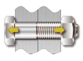
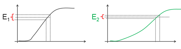
Types of joints
The type of joint on which we must tighten is a very important element, knowing the behavior of a bolt in relation to its stiffness is a fundamental aspect that allows us to avoid errors in the application of the tightening torque.
An elastic joint differs from a rigid joint mainly for the capacity of elongation at parity of applied preload.
The length of the bolt is one of the main characteristics for which a joint can be defined elastic or rigid, in principle a longer bolt is able to store more energy and consequently presents greater resilience to load drops.
For example:
We assume a loss of elongation of 0.1mm on two M36 bults 150mm and 300mm long respectively.
M36x150 > 0,45mm > 0,1/0,45 = 22%
M36x300 > 0,90mm > 0,1/0,90 = 11%
It should be noted that a loss of elongation of the bolt of 0.1mm determines a significant difference in terms of percentage pressure drop.
From a practical point of view, it is possible to establish that greater resilience to load drops decreases the possibility of errors in tightening, as shown in the graphs below (E1> E2).
Stiffness of the bolt and the connected elements
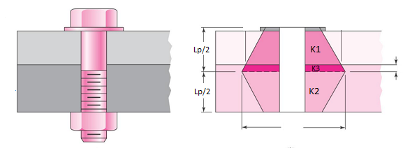
The topic of this paragraph deserves a separate article as it is extremely complex, however we try to understand in a very simplified way what are the concepts relating to the stiffness of the connected elements and the distribution of the load along the length Lp.
The stiffness of the bolt is a simpler argument both conceptually and as a mathematical calculation, the bolt is considered as the sum of two springs of different stiffness put in series, the first represents the part from under the head to the beginning of the thread, the second represents the threaded part subjected to the load, the calculation formula is the following:
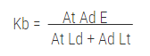
Kb: Bolt stiffness;
At: Area of the threaded section;
Ad: Area of the unthreaded section;
Lt: Length of the threaded part;
Ld: Length of the non-threaded part;
E: Modulus of elasticity (Young's modulus);
As for the elements interposed between the head and the nut, it is possible to establish that the total stiffness can be represented with springs placed in series (as for the bolt), the load distribution is instead more complex, precisely in the shape of a double cone (hollow for the presence of the bolt hole). The angle of inclination of the cone is considered to be 30 °.
In cases where the elements are of different thickness and above all of different materials, the elements must be considered as springs of different stiffness (K1, K2 and K3 where K is the stiffness), if instead the elements are of the same material they can be considered as a single element (even if the thicknesses will be different).
It might interest you:
Thread Pitch Chart - Metric and Imperial